Controlling GPIOs and LED
IoT Connector provides an easy to use rules based mechanism to control the reader GPOs and LED. User can create multiple rules and actions combo and save them on the reader.
The reader will monitor for those events and take the configured actions automatically.
Important
IoT Connector can only control the App LED (LED3) on the device.
Configuring using Web Console
The GPIO-LED configuration page can be accessed by navigating to Communication > Zebra IoT Connector > GPIO Config. This page allows the users to add any number of rules that will control the GPOs and the LED based on certain conditions.
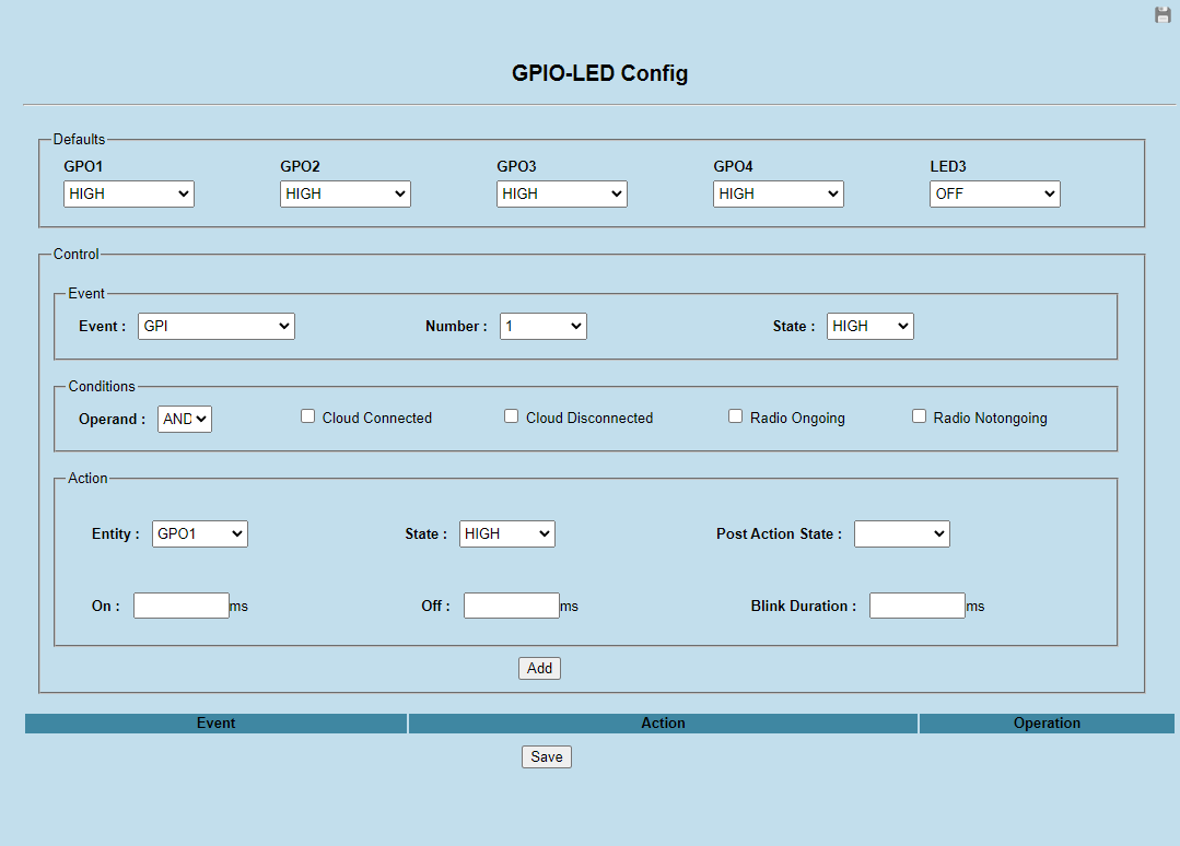
The page consists of the following sections:
Defaults : Specifies the default state of the GPOs and LED.
Event : Specifies the event of interest.
Condition: Specifies the additional conditions to check for before taking the action on an event.
Action: The action to be taken
The following table provides more info on each of the above items.
GPIO-LED Configuration Parameters Section
Control
Description
Values
Defaults
GPO1Specifies the default state of the GPO 1.
LOW,HIGHDefaults
GPO2Specifies the default state of the GPO 2.
LOW,HIGHDefaults
GPO3Specifies the default state of the GPO 3.
LOW,HIGHDefaults
GPO4Specifies the default state of the GPO 4.
LOW,HIGHDefaults
LED3Specifies the default state of the LED 3.
OFF,RED,AMBER,GREENEvent
EventSpecifies the event of interest.
GPI,Cloud Connect,Cloud Disconnect,Tag Read,Radio Start,Radio Stop.In case of a GPI events the Port Number and state can be specified.Note:- GPI Events are reported on GPI triggers.- Tag Events are reported on GPI triggers only if the corresponding GPI is set as the start triggerand inventory is ongoing.Event
NumberSpecifies the Port Number of the GPI. This is valid only if Event is selected as
GPIEvent
StateGPI.
HIGH,LowConditions
Cloud ConnectedIf checked, the configured action is taken only if the
IoT Connectoris connected to the endpoints.Conditions
Cloud DisconnectedIf checked, the configured action is taken only if the
IoT Connectoris disconnected from the endpoints.Conditions
Radio OngoingIf Checked, the configured action is taken only if the reader is currently trying to read tags (Start is issued).
Conditions
Radio NotongoingIf Checked, the configured action is taken only if the reader is not trying to read tags (Stop is issued).
Conditions
OperandANDOperand is selected, then the action will be applied only if all the conditions specified have been met.IfOROperand is selected, then if one of the conditions is met, the configured action will be taken.
AND,ORAction
EntityEntity to be controlled when the event occurs.
LED3,GPO1,GPO2,GPO3,GPO4Action
Statespecifies what state to put the control entity into.
HIGHorLOW.for LED, the State can be set toGREEN,REDorAMBER.Action
Post Action Statespecifies what State the Entity must be left in after performing the action.
HIGHorLOW.For LED, the Post Action State can be set toGREEN,REDorAMBER.Action
OnStatefield in Action section.A valid integer
Action
OffStatefield in the Action section.For LED, the Off state is when LED is OFF.A valid integer
Action
Blink DurationSpecifies the duration in milli-seconds for which to perform On/Off of the entity.
A valid Integer
Managing GPIO-LED Configuration
Once the required configuration parameters for GPO-LED control is entered in the UI, User can click on the Add button.
This will add the current configuration to the list of configuration at the bottom of the page as shown below.
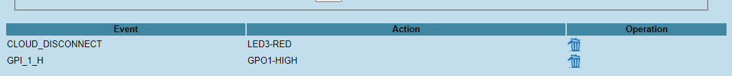
User can click on any of the added configurations to view the details. Upon clicking the Delete icon, the configuration will be deleted.
Once the required configuration is all set, then the user must click on Save. Only then will the changes be pushed to the reader.
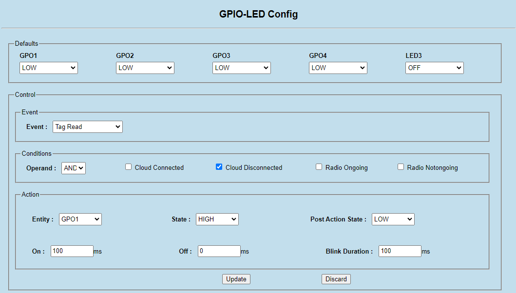
Example
In this example, the following control logic will be set on the reader.
By default all GPOs will be low and LED will be OFF
When a tag is read, if the cloud is disconnected, then GPO 1 will be set to HIGH for 100ms.
After 100ms GPO1 will be set back to LOW
The above configuration can be set on the reader as indicated below.